


Updated: 14
June 2017
VOLTS, AMPS, MOTORS,
LOCOMOTION
Ever wondered just what thyristor control and rheostatic brake really are; and why Networkers make those strange noises while accelerating? Well, here are the answers in a beginners guide to electric traction.
Basics - Volts and Amps
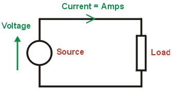 All electric circuits, no
matter how complex, boil down to being a source of energy
and a load. The current in a circuit depends on the
potential (or voltage) of the source, and the size of the
load, while the power consumed is the voltage multiplied by
the current.
All electric circuits, no
matter how complex, boil down to being a source of energy
and a load. The current in a circuit depends on the
potential (or voltage) of the source, and the size of the
load, while the power consumed is the voltage multiplied by
the current.In its simplest form, the load will be a resistor, with the energy dissipated as heat in the resistor. At the other extreme, however, the load could be a highly complex system. In traction, the energy is dissipated in the movement of the train mass and its load.
Further to this, the source could be one of two broad types - direct current (DC) or alternating current (AC). A DC voltage is one which always stays in one direction (such as from a battery), while an AC voltage alternates (such as the 240V domestic mains supply). The AC waveform illustrated is that most commonly used and is sinusoidal in shape.
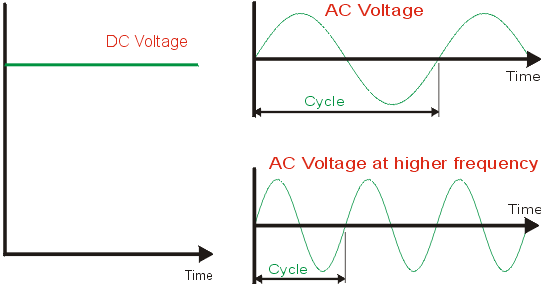
Alternating current also introduces another parameter - frequency. This is a measure of the number of cycles in a second and is measured in Hertz (Hz). As examples, two typical AC waves are shown, one at twice the frequency of the other.
Both types of supply voltage are used on Britainísí railways - mainline overhead electrification uses AC at 50Hz and 25 000V (or 25kV), while third rail uses DC at 750V.
DC Motors
As the name suggests, this is a machine which rotates when a DC voltage is applied to it. This type of motor has been widely used in electric traction for many years since it is relatively easy to control in order to achieve the desired motion. It consists of two main circuit elements; the armature (which rotates and forms the rotor) and the field (which is stationary and is part of the stator). Passing current through each of these circuits creates two magnetic fields which interact with one another to cause rotation.
The speed of the motor depends on the voltage applied to the armature and inversely to the current in the field (i.e. less field current, more speed), while the torque (rotational force causing acceleration) is dependent on the currents in both the armature and field. Once maximum volts have been applied to the motor, speed will not increase further, so at this point, part of the field is switched out. In its simplest application, there is only one stage of field weakening, but in more complex schemes there may be several.
The direction of rotation is determined by the interaction of the two magnetic fields, and is normally reversed by changing the direction of current flow in the field.
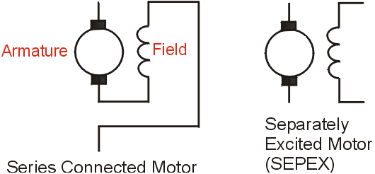
One particularly common configuration of the DC motor is where the armature and field are connected in series so that the same current flows in each. This has been used for many years since it gives a performance characteristic which is well suited to railway traction. However on more recent locomotives such as Classes 90 and 91, armature and field have been controlled independently to enable the characteristics to be tailored even more finely. This is known as separate excitation or SEPEX.
The fact that the armature rotates, means that electrical connection needs to be made to it. This is done by bringing the end points of the armature circuit together to form a cylinder of copper segments known as the commutator. This rotates between stationary contacts known as brushes (represented by the black blocks in the diagram). In practice to obtain smooth rotation, there are many armature windings and hence commutator segments and more than one pair of brushes and field coils.
Resistance Control and Camshafts
It was seen earlier that the DC motor can be controlled by varying the voltage and current applied to it. The simplest way of doing this is by adding or removing resistance in the motor circuit. A resistor in series with the motor will reduce the current flowing in the circuit and reduce the voltage across the motor terminals, and so the motor can be controlled by varying that resistance.
In practice, to achieve an acceptably smooth control of the motor, many different resistors are progressively switched in or out. This is generally achieved by using a rotating camshaft fitted with cams profiled to switch the various resistors in the correct sequence determined by the camshaft position which is in response to the driverís operation of the controls.
This is the control method used on stock built for running on DC routes up to the late 1980s; with Class 455 being the last units supplied to BR of this type. When traveling on this type of stock, it is possible to detect the steps in resistance during the early stages of acceleration. It can also be possible to hear the switches operating (this is especially so on older London Underground stock).
Transformers
Power transmission is most economically performed at high voltage so as to reduce the current and hence reduce the size of costly conductors. The standard that has emerged for AC electrified railways is 25,000V (25kV) at 50 Hz, however this is too high for direct use on a locomotive or EMU. An on board transformer is therefore used to step this voltage down to a more practical working level. On locomotives, the transformer has most often been mounted inside the body, while on Class 91 it is on the underframe, as it is usually found on EMUs. It is this component that gives rise to the steady hum on AC vehicles, just as much smaller transformers can also cause a similar hum in mains operated domestic appliances.
On early AC stock, the various steps in voltage to control the motors, were obtained by having a range of tappings on the transformer. A mechanism known as a tap changer would then select the appropriate tap as the driver accelerates the train.
In more recent years, transformer outputs have become fixed with voltage control being done electronically (see later) thereby giving significant simplification to the transformer with consequent reduction in maintenance requirements and improvements in reliability.
 Rectifiers
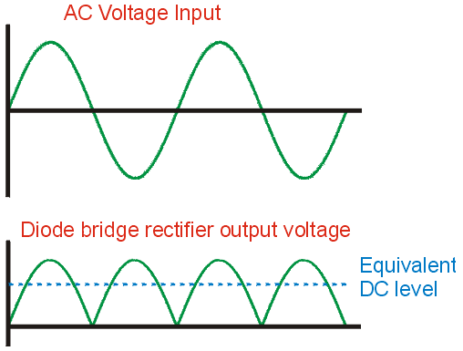
 Having arrived at a stepped down AC voltage, this needs conversion before it can be applied to the DC motors. To do this, a circuit known as a rectifier is employed. The simplest form of rectifier uses an electronic device known as a diode which only permits current flow when the voltage applied to it is in one direction. A number of diodes can be configured into a circuit known as a bridge rectifier which effectively turns all the negative parts of the applied voltage waveform into positive ones. In this way, a rough DC is produced which, when smoothed by a filter circuit, can be fed to the traction motors.
Thyristors
In the last 20 years (87101 was the first in the UK), a more advanced electronic device known as a thyristor has been used. This effectively acts like a diode in that it only permits conduction in one direction, however the point at which it starts conduction can be controlled by application of a control pulse to a third terminal on the device called the gate. The thyristors are also configured in a bridge circuit to provide controlled rectification, in which the turn on point is often referred to as the phase angle. Turn off comes automatically at the reversal of the incoming AC waveform, a feature known as natural commutation.
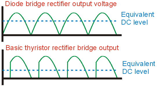 In this way chunks are taken
out of the rectified waveform meaning that the equivalent DC
output voltage (i.e. the average level) is controlled. The
larger the phase angle, the lower the DC output voltage.
 This development introduced a number of advantages. Firstly, as mentioned earlier, the transformer becomes much simpler; but secondly, a smoother stepless control of the motors is now possible which is especially advantageous on locomotives when adhesion is poor and wheelslip is likely.
Phase angle control with thyristors is used on Class 90 and 91 locomotives as well as on AC only EMUs from Class 314 to Class 321.
Gate Turn Off (GTO) Thyristor
A further advance in silicon semiconductor technology is a thyristor that can be switched off as well as on. This is known as the Gate Turn Off Thyristor or GTO for short. Here, the application of a positive control pulse to the gate will turn it on, while a negative pulse turns it off again. This opens up further possibilities.
Choppers
The main early use of GTOs in traction systems was in chopper circuits to provide a variable level output DC voltage from a DC input voltage, thereby eliminating the need for resistance control of DC motors and giving increased efficiency. It does this by switching the input voltage on and off depending on what output voltage is required; the longer the chopper is switched on, the higher the output voltage. The time that the chopper is switched on for is known as the on time, while the ratio of on to off time is the mark to space ratio or chopper ratio. Choppers are usually operated at a fixed frequency (300Hz in the UK), meaning that the beginning of each on time is a fixed interval of time apart known as the period.
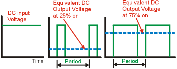
The voltage to the DC motor can thus be applied smoothly from a DC supply starting at a low on ratio building up to 100% as speed increases.
The first example of chopper control in the UK was on the dual voltage Class 319 in which the 3rd rail supply voltage is fed direct to the chopper when on DC operation, and the output of a diode bridge rectifier is fed to the chopper on AC operation. The DC only Class 456 is fitted with similar chopper equipment, as is the dual voltage Class 325.
When traveling on the PMOS of a Class 319 (the intermediate car with the pantograph), the chopper is the source of the buzz that is heard when accelerating, the sound of which changes progressively as the chopper ratio increases as speed builds up.
AC Motors
The most significant disadvantage of the DC motor is its cost which is largely attributable to the work involved with the commutator, both to build and maintain.
AC motors provide a simpler alternative of which there are two main types - synchronous and asynchronous of which the latter has been most widely adopted for electric traction. Here 3 phase AC is applied to the stator, creating a rotating magnetic field which draws the rotor round with it, without need for external connections to the rotor.
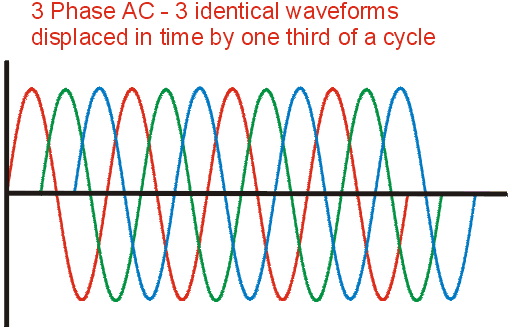
The speed of rotation is determined by the frequency of the AC applied, while the torque developed depends on the current and relative speed of the rotor and the rotating magnetic field. This, and other factors, means that the control of AC drives becomes very complex and variable speed, variable torque drives such as required for traction have only become practical in the last 10 years.
GTO Inverters
A circuit which converts DC into AC is known as an inverter and is effectively the reverse of a rectifier bridge. The first used in the UK (Class 465) use GTOs and are controlled by a technique known as Pulse Width Modulation (PWM). Here the DC input is chopped up for narrow time intervals (pulse width) proportional to the magnitude of the AC waveform required at that particular instant (i.e. the pulses are widest at the peak of the AC waveform).
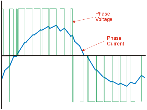
Here it can be seen that the quality of the output current will be determined by the number of pulses in a cycle - the more pulses, the less the sawtooth effect in the current waveform.
In practice the number of pulses is limited by the switching capability of the GTO whose maximum is typically 900 operations per second. If the AC output of the inverter was only required to reach a relatively low frequency, the number of pulses per cycle could be quite high without exceeding the GTO limit; however at higher inverter output frequencies, the number of pulses need to be reduced. Fortunately the characteristic of the motor is such that this is not critical.
Now, remember that the speed of an AC motor is determined by the frequency of the AC applied to it, this means that the inverter output frequency must vary over a wide range (in the region 0 - 200 Hz depending on the motor design, max speed of vehicle and gear ratio between the motor and wheel). Consequently, practical GTO inverter drives, such as on Classes 323, 365, 373, 465 & 466, employ complex switching strategies where the number of pulses per cycle is changed in stages as the inverter frequency increases and the train speeds up. This is why this stock makes the curious gear changing noises during acceleration (sound clip of Class 465 here). Indeed, the various stages of switching are known as gears for this very reason.
IGBTs
The Insulated Gate Bipolar Transistor (IGBT) is the latest generation of power electronic device to see use in traction drives. These devices can be switched much faster than their GTO predecessors (in excess of 2000 operations per second) and require simpler control electronics to switch them on and off. This higher switching rate eliminates the need for the "gears" in inverter outputs which also makes the control less complex and results in an audibly smoother acceleration. The first stock in the UK to employ IGBTs in their traction drives were Class 332 Heathrow Express in both the inverter and force commutated bridge circuits (see below). The subsequent introduction of Classes 333, 334, 350, 357, 360, 375, 376, 377, 390, 444, 450, 458 and 460 now sees them in widespread use across the UK. Also, the diesel electric Class 220 and 221 Virgin Voyager fleets and Class 222 Midland Mainline Meridian and Hull Pioneer units employ IGBT traction inverters.
Force Commutated Bridges
A disadvantage of diode and especially thyristor rectifiers, is the fact that the current drawn from the supply always lags behind the voltage. This displacement is referred to as the power factor and the power generation people would really prefer users to take their electricity at unity power factor, where the two are totally in line. Recent advances now make this possible with the use of a force commutated bridge.
If the term "naturally commutated" is recalled from thyristor bridges, it will be understood that, in a force commutated bridge, the thyristors not only have their switch on controlled, but their switch off as well. By using GTOs or IGBTs controlled with a PWM switching pattern similar to an inverter, current can be brought into line with the supply voltage. This can result in reduced electricity bills and hence reduces the running costs of the stock.
Such equipment is presently fitted on Classes 92 & 323 using GTO devices and IGBTs on Classes 333, 334, 350, 357, 360, 377/2 and 390.
Rheostatic Brake
As well as making trains move, electricity can also be used to make them stop since motors act as generators when energy is put into them as rotation. In rheostatic braking, the generated energy is simply dissipated in a brake resistor otherwise known as a rheostat. This can give considerable long term savings in brake pad wear and tear. On modern stock the energy dissipated in the brake resistor is controlled by either a GTO or IGBT chopper circuit. In certain positions on certain vehicles on the Class 220 - 222 stock the hum in the cables leading to the roof mounted brake resistors can be heard.
Stock fitted with rheostatic braking includes all the AC electric locos, Class 373 and EMUs such as 465, 365, 315, Pendolino Class 390s, 200 and 221 Voyagers, 222 Meridians and Pioneers as well as all the recently supplied Desiro, Electrostar and Juniper fleets.
Regenerative Brake
This is where the train actually returns energy back to the supply system during braking. On DC electrified railways it has not generally been practical to return it to the National Grid (although inverting supply substations are now possible with high power semiconductors), but it can be used by other trains that are motoring. Consequently DC regeneration is particularly suited to intensively used commuter railways. If there are no other such trains on that particular supply section at the time (as will be detected by increasing supply voltage as the train regenerates) the line is said to be non-receptive and the train will revert to rheostatic brake.
Concerns that DC regenerating trains would compromise power supply safety protection systems initially prevented the introduction of regenerative brake on DC routes in the UK, even though new trains had the capability (Class 465 was the first). Once it was verified that protection would not be significantly affected, DC regenerative brake has been introduced on fleets operating on the DC network.
On AC electrified railways, regeneration is more complex since a 50 Hz AC waveform needs to be created and hence this has only become practical with the advent of the force commutated bridge. AC regenerated energy may be used either by other trains motoring nearby, or can be returned to the grid, therefore the AC system is predominantly receptive. As the AC overhead is fed from different phases of the National Grid, the wire is fed in distinct sections with an isolating section of wire known as a neutral section at regular intervals along a route. In a similar manner to a DC system becoming non-receptive, AC regeneration is clearly not possible through a neutral section, so rheostatic braking will be introduced while the train slows through the neutral.
Tony Woof B Eng C Eng MIEE
Copyright 1998, 2002, 2005, 2017
What's got what is a guide to the equipment employed on UK mailine electric rolling stock.
